NASAM Update – 6th Jan 2025
In This Edition
Summary of Contents
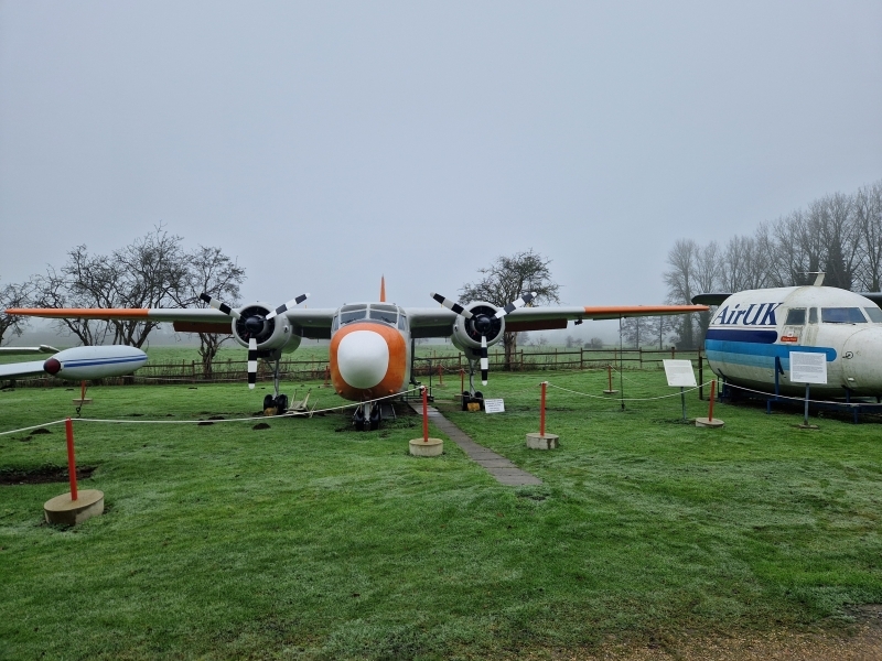
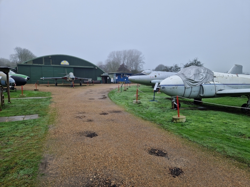
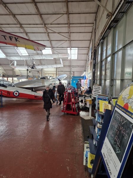
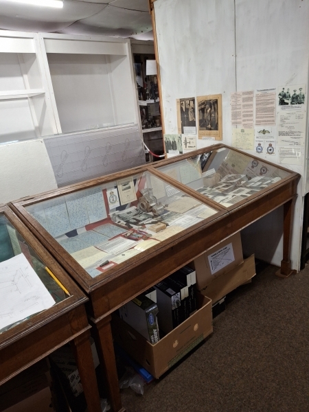
In this edition of the blog “Museum News“, we have a few photos from Steve on those two days in December, after the Christmas break, when we opened to enable people to enjoy a breath of fresh air and see off the excesses of festivities.
We also have details of the opening date in 2025 (19th Feb) and links through to the details of the admission prices for 2025.
From the Teams “Inside and Outside – The Museum“; firstly, we have a December update from the Chippies, Michael F providing an insight into the repairs and refurbishment of the roof in Room 3, a lengthy but necessary job.
Next in this section from the Teams, we have a piece from Tony, in Archives, who introduces us to some of the education classes at the Museum. Tony runs basic courses in Navigation, and the first of his articles is Dead Reckoning. There will be more to come from Tony later as he looks at the navigation artefacts that we have in our Archive Section.
Pete S
Museum News
General news from the Museum
Last of the Year
The last days for the museum to be open in 2024 have now happened. Around 100 people visited across the two foggy, but mild (for December) days. We had a good turn out from volunteers, mostly trying to escape from Christmas.
The two days were the last days of entry by donation, next time we open on February 19th we will be charging for admission.
Steve
(Photos) Last of the Year
(For more information on admission charging, please click on the button below)
Click to see theMUSEUM CHARGES
![]()
Museum Reopening
The Museum will reopen after our winter maintenance period on Wednesday, the 19th of February 2025. We will return to our usual hours from 1000 through to 1600, and the opening days will be the same as in 2024 on Wednesdays, Saturdays, Sundays and all Bank Holiday Mondays.
More information can be found on our events page, where Graham explains things in more detail. To go to the events page, click on the “Welcome Back” below:
Pete S
Inside and Outside – The Museum
Information from the various teams
Room 3 Updates
Room 3 Part 43 (or thereabout)
Yes, the Chippies have been in Room 3 – again! Hopefully, this saga is coming to an end, but maybe it’s one of those never-ending soap operas – who knows?
The observant visitor to Room 3 may have noticed what appeared to be a pit prop holding up the ceiling and wondered if they were lost in a Mining Museum rather than one dedicated to Aviation. Wonder no more….
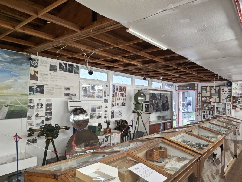
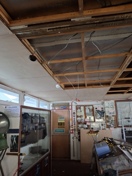
At some point, lost in the mists of time of the last year (that is, I can’t remember the date, just the incident), one Tuesday morning, the Chippies received a garbled message. It was from the Chairman via an intermediary saying that the ceiling in Room 3 had fallen down, and could we fix it – pretty, please? So Ash and Michael F inspected said ceiling and found that indeed two roof panels were adrift and hanging precariously over the searchlight mirrors.
With some ingenuity (yes, we big ourselves up, the Painters do, so why shouldn’t we) they devised some emergency measures to reattach the panels to the rafters above. Adding a belt to the braces, they rammed a length of reclaimed 2×2 vertically to create the pit prop. And so the ceiling was left, safe but looking tatty and with other panels appearing somewhat dodgy.
Fast forward to late September, and the Big Boss (Gary, the Manager) came around touting for ideas for the Winter Maintenance programme. “Aha,” cried the Chippies, “that Room 3 ceiling looks pretty tatty and could come down again. Maybe we should replace the whole lot?” “I agree” replied the Boss “but I think that might break the budget. Get me a price”. So Chippies sallied forth again (there is a well-worn path between their Workshop and Room 3 – in fact, it is said they can unlock and open the doors from the Shop via Room 2 blindfold) and counted ceiling panels – 48 4ft x 4ft squares. A friendly call by Dave H to Betts provided the answer, duly presented to the Boss.
Two or three weeks later, the answer came back. “Do it!” With the proviso that everything was complete by February 2025 ready for opening – ceiling, electrical changes, painting, the lot. And so, at the beginning of November, work commenced. “What’s this? I hear you say, “the Museum didn’t close until the end of November.” Well Steve B, anxious to get Room 3 finished, agreed to close it a month early to give the Chippies extra time.
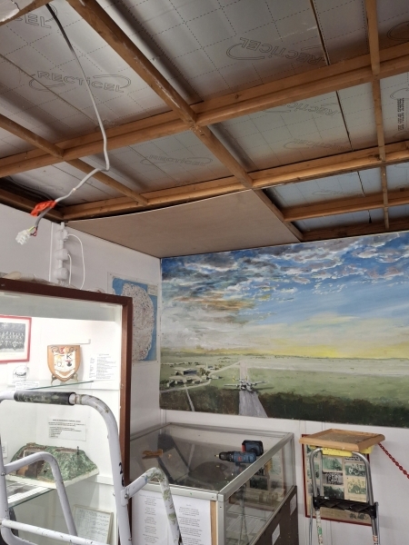
Work really started in late October, when Dave H placed the first order for half of the ceiling panels and insulation panels – we didn’t want to clutter up the Workshop too much and the Container got full quickly, so some also went in the closed off section of Room 3. We also took down a single panel to properly inspect the space above the ceiling. Fortunately, the rafters and trusses looked sound, though we did discover a sub-framing which made 2ft x 2ft squares. This gave us extra support for the ply panels but meant the insulation boards wouldn’t fit easily.
So came November 5th. No fireworks in Room 3, but down came 16 panels. And the plethora of fixings that had been used over the years in attempts at repairing the ceiling. When it was originally built, 20 to 50 years ago according to various sources, they appeared to use nails. Since then, they were screwed, with steel and brass screws; slotted, Philips and pozi heads: more nails, and even staples! The fibreboard panels came away easily but left behind most fixings, so the laborious task of removing them followed.
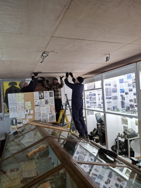
This marathon job required additional reasonably agile manpower. So Ivor and Tony C joined Ash and Michael F. Most workdays saw combinations of two or three or all four working in the poorly lit (the Leckies took down most of the lights) cold (the fire door was always open) conditions. Ah yes, the Leckies – quite often, David Hines, Pete and Eddie were on hand disconnecting and removing lighting or providing temporary lighting. And they even leant us one of their ladders and helped take down a large section of ceiling. It was one big team effort.
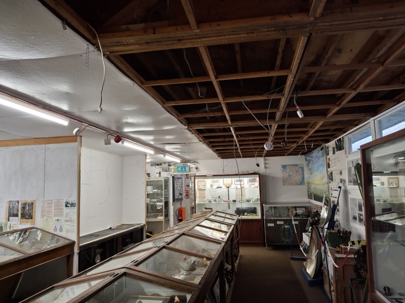
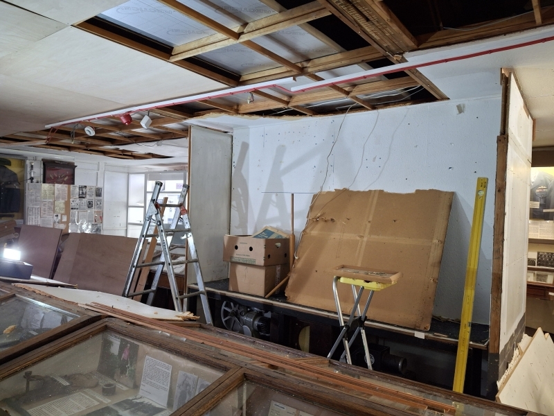
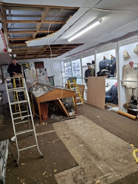
Now the original plan called for one section of the old ceiling to stay. The end of the right-hand cabinets as you entered was a floor to ceiling display cabinets, unlike the rest of the cabinets which are low, angled display cases. We originally planned to leave the panels above it but put new ceiling all around. Then Steve B announced that he wanted the (to be honest) ugly block to go and for the Chippies to make new ones like the others. Well, more demolition derby! It was like watching children at the funfair allowed to make mayhem! Down they came and the room looks so much more spacious.
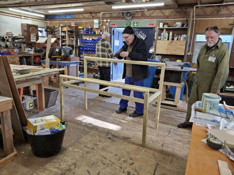
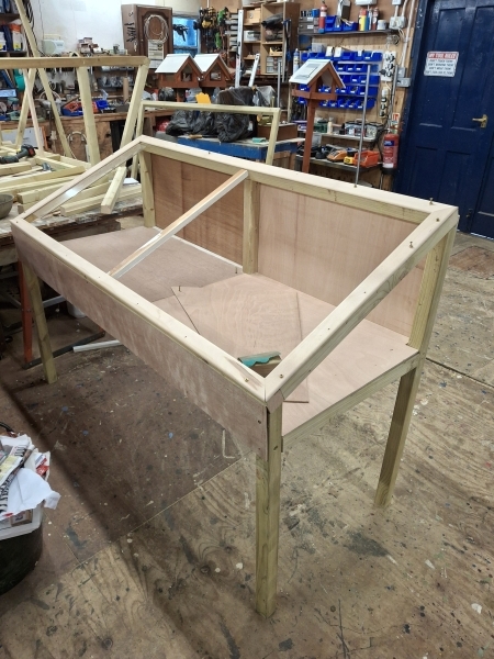
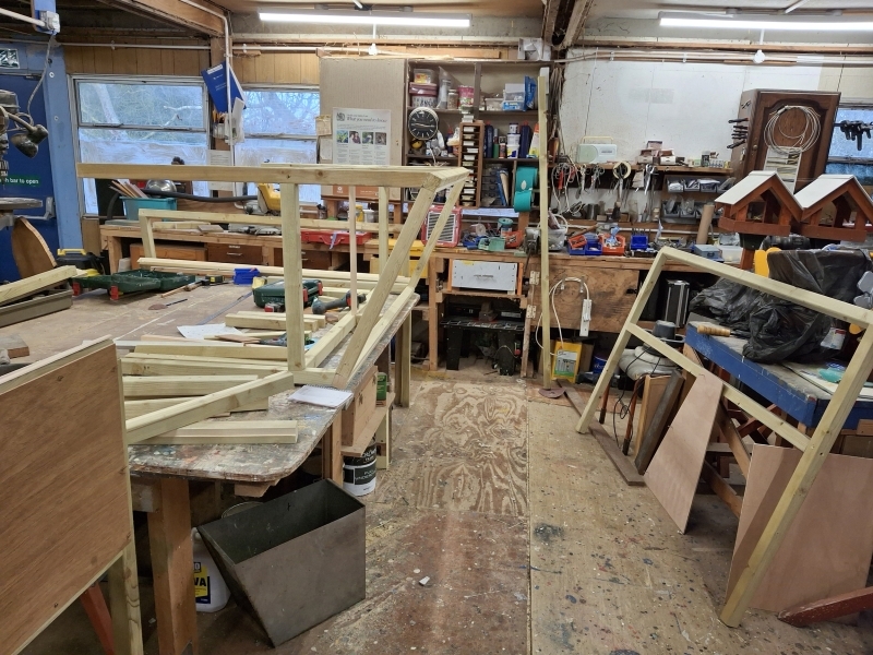
Dave H, champing at the bit back in the Workshop and wanting to become involved, seized the opportunity to build the four new cabinets. Steve stipulated that he didn’t want any of Dave’s “industrial look” but to similar dimensions as the existing ones. Fortunately for Dave, they have 2 inch margins, so he could use his favourite material – 2×2 section wood. He beavered away at his task, routing out for the clear inlays, cutting at angles, using mouldings to take the “industrial ” edge off. Prototype made, he struck out on mass, providing three more.
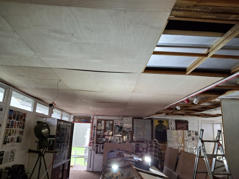
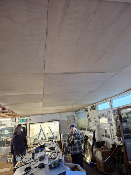
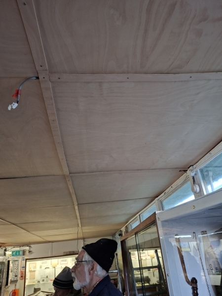
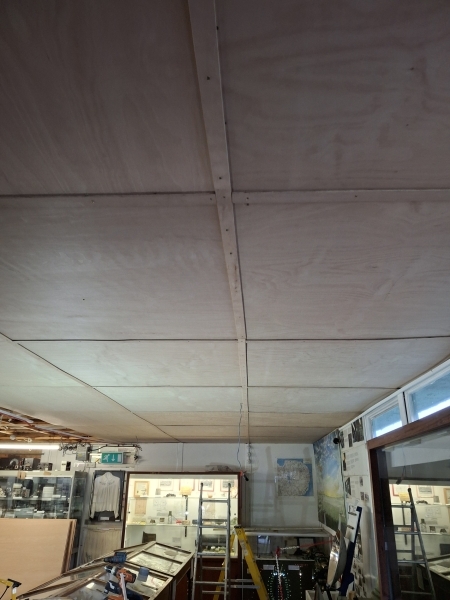
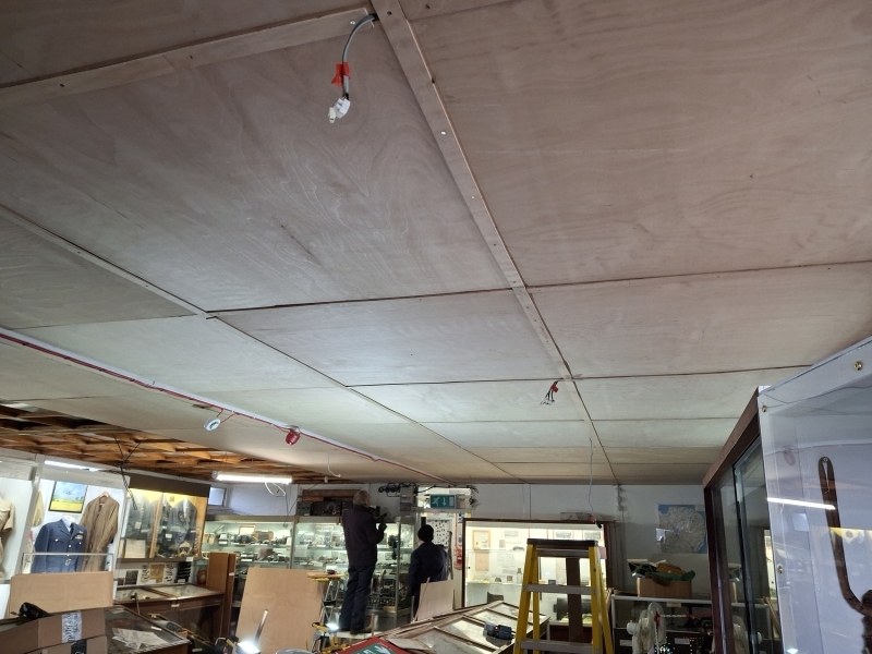
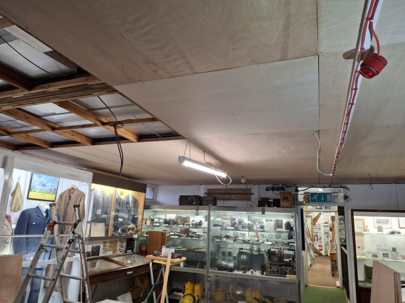
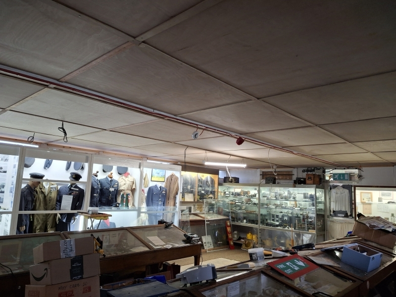
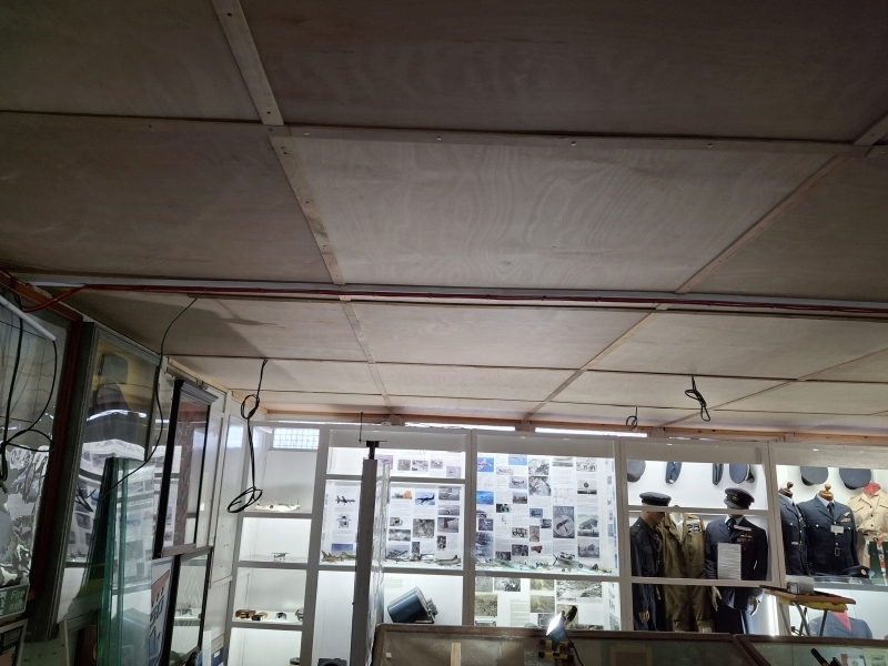
So November passed into December and the Christmas Break and where are we now? Well the ceiling is complete! All 48 panels are up. Strips of ply cover the joins between panels – hiding the misfits, yes, but also proving extra support to the panels. One new cabinet is made and partly encased. Three more cabinet frames are built. The Painters move into Room 3 in January to start undercoating it. When they are done, the Leckies move back in to finish the lighting. So it should be done ready for opening in February, what we were asked to do. And a huge thanks from the Chippies to Ivor, Tony C, David Hines, Pete and Eddie for their help in putting up the ceiling.
Michael F
(Photos) Room 3 Update
![]()
Dead Reckoning (DR) 1: Basic Principles
We think that our display of DR instruments in Archive 2 is unrivalled and more than merits a look-in. With this in mind I’m writing a series of articles for the Blog, each article being devoted to one instrument out of our range, in chronological order. In this first article, I’ll cover the basics of DR navigation and introduce the common terms.
Firstly, a bit of revision:
Aircraft fly on bearings, which are angles measured clockwise from due North. For example, the bearing of due East is 090°
Wind information comes in 2 parts: its speed and the direction it comes from. For example, a North wind blowing at 20 mph would be advised as 000°/20.
Right, off we go! Imagine that I want to fly to a destination due East of my current location. I set my compass on 090° and take off; unknown to me, there is a North wind blowing. The effect of this wind is to push me sideways, although my heading is unaffected. I am still flying due East but slipping ever southwards of my destination. This situation is shown in the diagram below.

This is a vector triangle:
- AB represents the course and airspeed
- BC represents the wind speed and direction
- AC represents the track which is the actual path of the aircraft over the ground.
It is also a scale diagram, the lengths of the lines representing the respective speeds. The length of AC is the ground speed of the aircraft which is used to calculate flight times.
Since the triangle is a scale drawing, we can solve some navigation problems by drawing. As long as we have any 4 of the 6 components needed, we can find the missing 2 by constructing the triangle.
Here’s an example, taken from Mansel Williams’ 1943 booklet ‘Air Navigation Plotting’:
‘The airspeed of an aircraft is 220 mph and the wind velocity is 320°/36 mph. Find the course to steer to make good a track 071°. What is the ground speed?’
Solution:
On a sheet of A4, draw a rough diagram at the top of the page; this enables you to position the scale drawing so that all the dimensions are included.
Choose a scale for your drawing; say, 1 cm : 20 mph.
At the chosen spot (A), use a protractor to draw a North line – known as a ‘meridian’.
From A, draw a long line at an angle of 71°; this represents the track.
Place the centre of your protractor on A, ensuring that 0° is aligned along the meridian. Find 320° on the scale – you will need to turn a semicircular protractor around – and make a mark on the page.
Draw a line joining this mark to A and extend it a few centimetres.
Measure from A 1.8 cm (36mph) along this extended line and make a mark (B).
Use your protractor to draw another meridian at B.
Open your compass to 11 cm (220 mph). Place the point on B and make an arc to cut the track line from A. Join this point (C) to B; BC is the course line.
Use your protractor and the meridian at B to find the course bearing.
Measure AC and convert to mph; this is the ground speed.

The answers are: Course 062°, groundspeed 230 mph.
If you are ± 1° on the bearing and/or ± 2 mph for the groundspeed you have done remarkably well!
You can imagine the difficulty of doing all your nav problems with scale drawings … !
So, next time we’ll have a look at chartboards, the first attempt at producing a DR instrument.
In the meantime, here’s another of Mansel Williams’ problems for you to have a go at; bonne chance! (Answers next time).
‘The wind velocity is 090°/37 mph. What course must be steered to maintain track 134° if the airspeed is 130 mph? What is the groundspeed?
Tony L
The Repeat Info
Here we are, the start of a new year, and despite the fact that we will now raise some monies through our admission charges, the repeat information is still here, I’m afraid, and I make no apologies for keeping his section in our blog. We are a charitable organisation relying on some grants and monies from the public to keep us going. Any help we receive is gratefully accepted and enables the museum to continue in our mission “To conserve, preserve and promote the history of aviation in East Anglia, whilst providing a fun, family-friendly and interactive museum, promoting education and remembrance of the events of the past“.
Are you thinking of helping ??
 We save money by having a dedicated group of volunteers that keep the museum and the exhibits both manned and maintained. We hope therefore a few people may consider helping in the ways below.
There are three easy ways to help: Help by becoming a Museum Member, also by Volunteering to help at the museum, or by Donating to assist in our running costs. Please click on the appropriate button below to access the appropriate information:
Keep Up To Date
![]() To keep up to date with further information, please keep an eye on our Social Media (see the Social Media buttons at the foot of this blog) or click on the button below to be notified by email of any upcoming changes by seeing the latest blog.
To keep up to date with further information, please keep an eye on our Social Media (see the Social Media buttons at the foot of this blog) or click on the button below to be notified by email of any upcoming changes by seeing the latest blog.


